


Ask the AI Tutor
Need help with Electricity - Electrical Circuits 03? Ask our AI Tutor!
AI Tutor - Lucy
Connecting with Tutor...
Please wait while we establish connection
You might find a symbol when buying a bulb for a lamp - but do you know what symbol to expect?
Electricity - Electrical Circuits 03
Practise GCSE electricity questions on parallel circuits, current, voltage and resistance while you test your understanding of circuit rules used in real exam style questions.
1 .
What does this symbol depict?

Lamp
LED
Resistor
Diode
Converts electrical energy usefully into light but wastes a lot of energy as heat
2 .
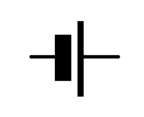
What does this symbol depict?
Diode
LED
LDR
Cell
Several cells joined together are called a battery
3 .
What does this symbol depict?

Diode
LED
LDR
Cell
This allows electricity to pass in only the forward direction
4 .
What does this symbol depict?

LED
LDR
Diode
Variable resistor
The resistance of a light dependent resistor changes according to the light intensity around it
5 .
What does this symbol depict?

LED
Diode
LDR
Resistor
Converts electrical energy into light energy much more efficiently than a filament lamp
6 .
What component does this graph typically represent?

LDR
LED
Resistor
Diode
A resistor has a constant resistance at a constant temperature regardless of the voltage or current applied to it and as such forms a straight line when values of current and voltage are plotted on graphs
7 .
What does this symbol depict?

Resistor
Diode
Bulb
Cell
These restrict the flow of charge in a circuit
8 .
What does this symbol depict?

Resistor
Variable resistor
LDR
LED
These are useful for controlling the speed of an electric motor or the brightness of a lamp
9 .
What component does this graph typically represent?
Diode
Filament bulb
Resistor
Variable resistor
As the voltage across a filament bulb gets bigger, the filament gets hotter and as a consequence its internal resistance increases, causing the graph to become curved at a higher voltage. A filament bulb does not obey Ohm's law
10 .
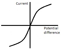
What component does this graph typically represent?

Diode
LDR
LED
Resistor
The shape of graph a diode creates is easily recognisable as it only allows current to flow in one direction


**Unlimited Quizzes Await You! 🚀**
Hey there, quiz champ! 🌟 You've already tackled today's free questions.
Ready for more?
Ready for more?
🔓 Unlock UNLIMITED Quizzes and challenge yourself every day. But that's
not all...
not all...
🔥 As a Subscriber you can join our thrilling "Daily Streak" against other
quizzers. Try to win a coveted spot on our Hall of Fame Page.
quizzers. Try to win a coveted spot on our Hall of Fame Page.
Don't miss out! Join us now and keep the fun rolling. 🎉
**Unlimited Quizzes Await You! 🚀**
Hey there, quiz champ! 🌟 You've already tackled today's free questions. Ready for more?
🔓 Unlock UNLIMITED Quizzes and challenge yourself every day. But that's not all...
🔥 As a Subscriber you can join our thrilling "Daily Streak" against other quizzers. Try to win a coveted spot on our Hall of Fame Page.
Don't miss out! Join us now and keep the fun rolling. 🎉
© Copyright 2016-2026 - Education Quizzes
Work Innovate Ltd - Design | Development |
Marketing